Research Projects
Please see the publications page for further information about the research projects and figures below.
Examples of Recent/Ongoing Projects
Note: This list is far from complete--just a selection of topics to highlight some research areas the PAC Lab has explored.
Research by Josh Robbins, Ph.D. Student:
Motion planning is a key task in making vehicles, like self-driving cars, work autonomously. It acts as a middle step between the big-picture decisions about where the vehicle should go and the control systems that make the vehicle actually follow the path. The algorithms involved in motion planning use local information about the environment, which can be complicated, to create a safe path that avoids obstacles. These algorithms also need to make sure the vehicle moves smoothly and comfortably, while reducing risks or dealing with uncertainty. Since motion planning happens in real-time, the algorithms need to be fast and efficient to work properly.
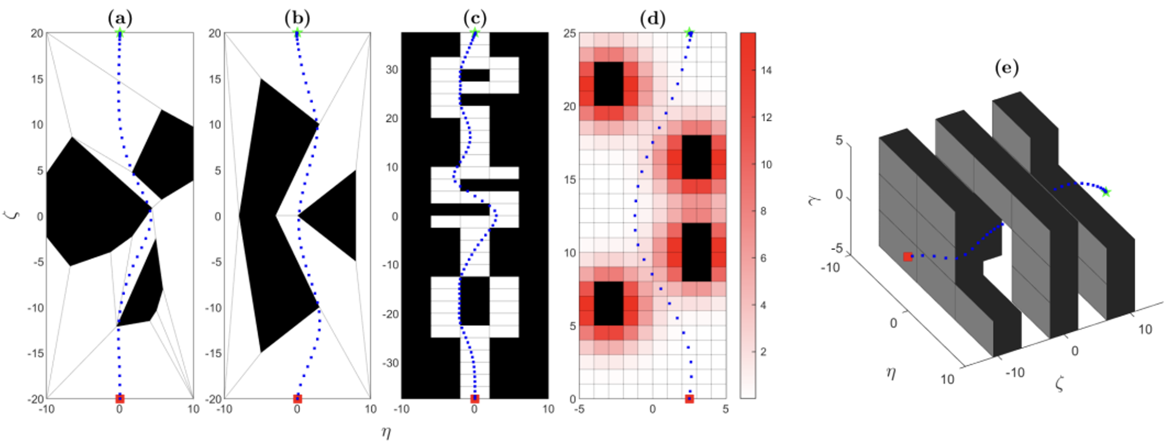
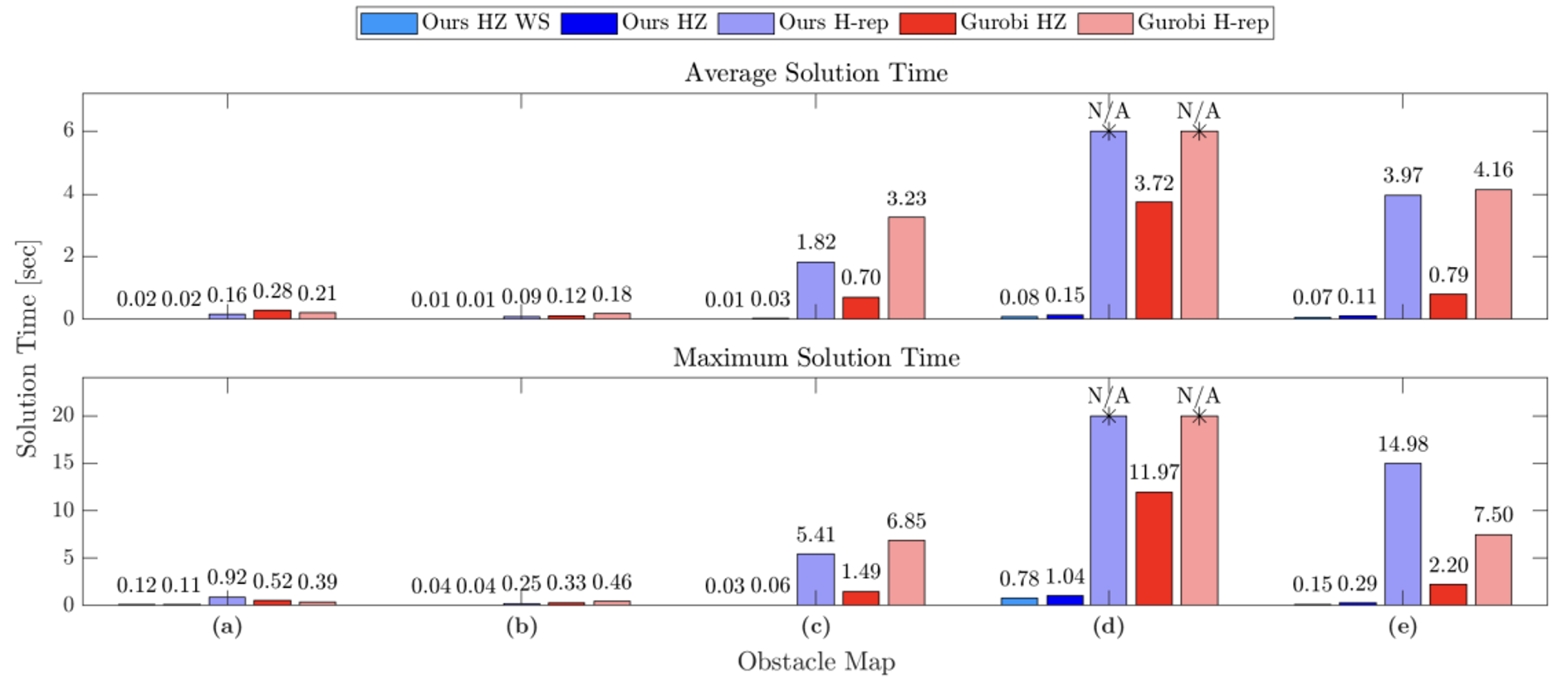
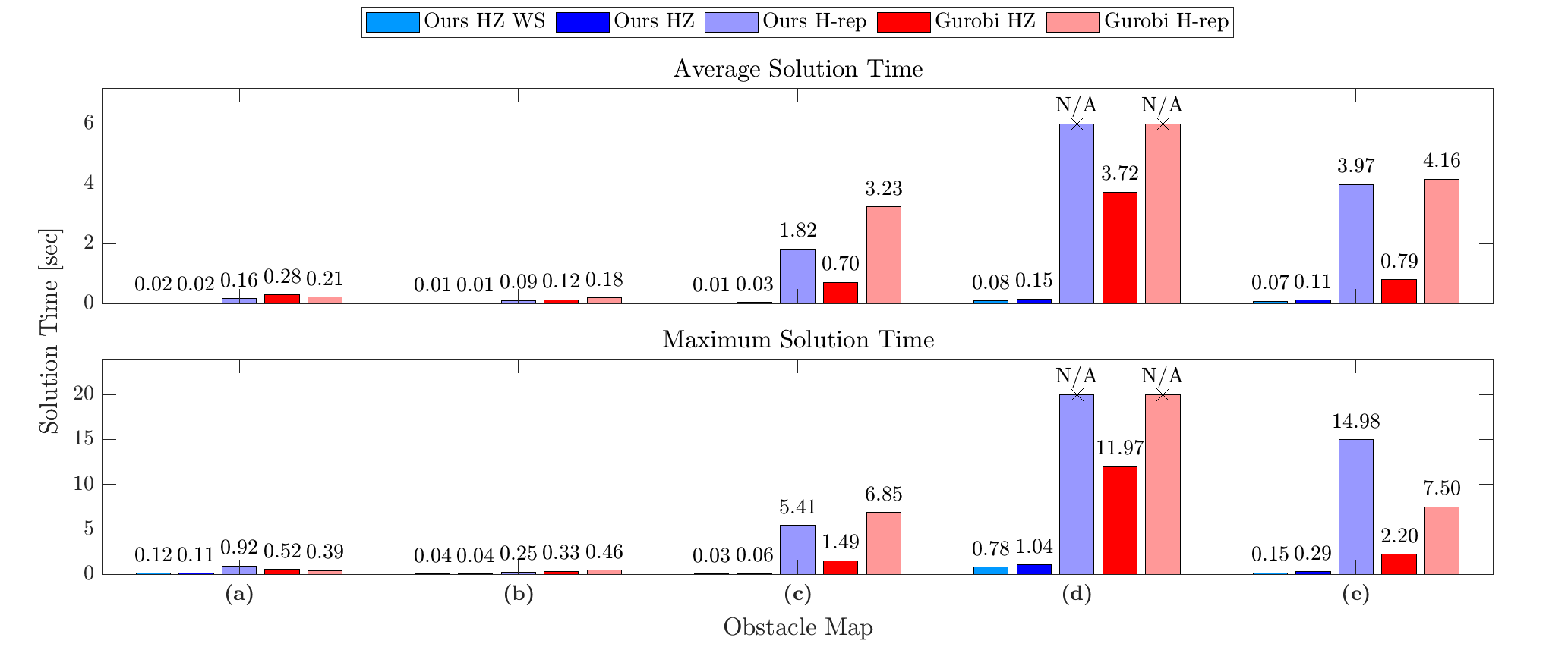
We have developed an optimization algorithm for solving motion planning problems that takes advantage of a special way to represent the obstacle-free space, called a hybrid zonotope. Figure 1 shows simulated trajectories using our optimization algorithm. Figure 2 shows the solution times for the trajectories from Figure 1. In Figure 2, HZ denotes the hybrid zonotope constraint representation, while H-rep denotes halfspace representation, which is a more conventional approach. Gurobi is a state-of-the-art commercial solver. Solution times are reduced across the board using our solver with a hybrid zonotope constraint representation, often by one or more orders of magnitude. This demonstrates the utility of our approach for solving complex motion planning problems in real-time.
Research by Jonah Glunt, Ph.D. Student:
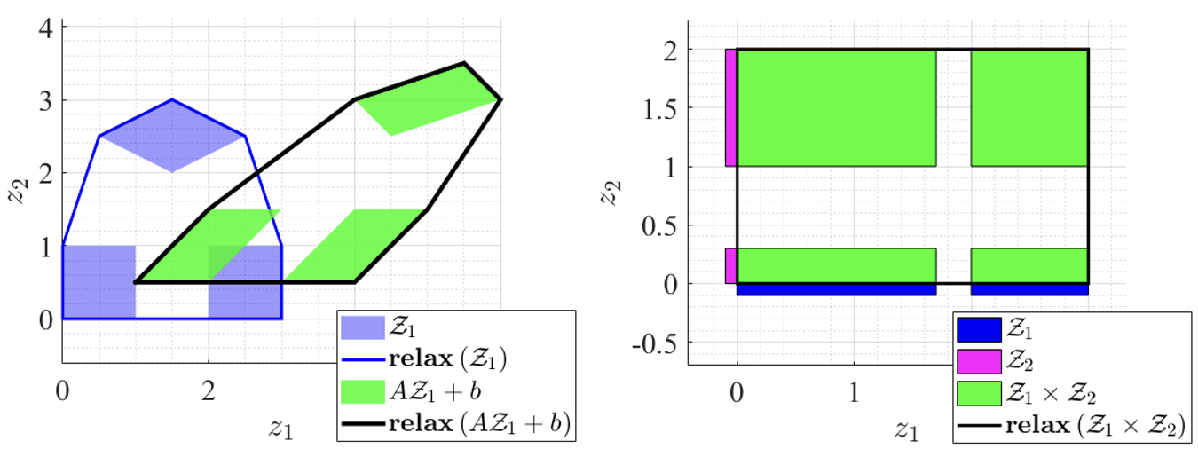
Mixed integer set representations, and specifically hybrid zonotopes, have enabled new techniques for reachability and verification of nonlinear and hybrid systems. Mixed-integer sets which have the property that their convex relaxation is equal to their convex hull are said to be sharp. This property allows the convex hull to be computed with minimal overhead, and is known to be important for improving the convergence rates of mixed-integer optimization algorithms that rely on convex relaxations.
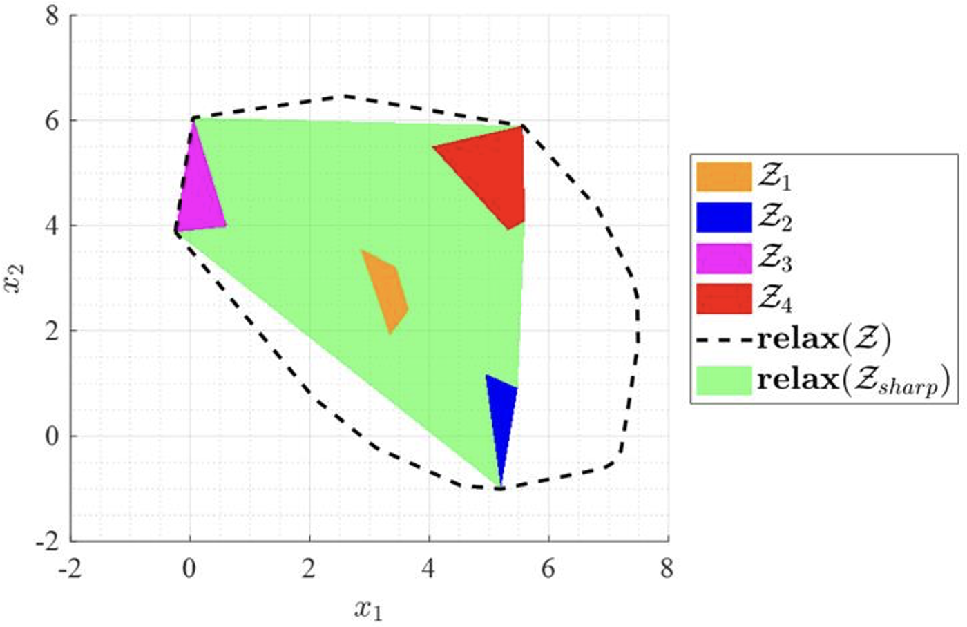
This research examines methods for formulating sharp hybrid zonotopes and provides sharpness-preserving methods for performing several key set operations. It then shows how the reformulation-linearization technique can be applied to create a sharp realization of a hybrid zonotope that is initially not sharp. A numerical example applies this technique to find the convex hull of a level set of a feedforward ReLU neural network.
This work examines two key approaches to making a set representation sharp:
1) Sharpness-Preserving Set Operations:
One technique to produce a sharp representation of a set is to construct the set using set operation identities that preserve or induce sharpness. For example, the operations of Minkowski sum, affine mappings, and Cartesian product all preserve sharpness (the latter two are proven within this work). This research also presents a novel identity for the union of hybrid zonotopes that preserves sharpness.
2) General-Purpose Technique:
An approach from the literature, called the reformulation-linearization technique can be applied to any hybrid zonotope to tighten the relaxation or even make the set sharp. This technique causes an exponential complexity growth, but can be applied on low-complexity hybrid zonotopes.
Research by Joshua Robbins, Ph.D. Student:
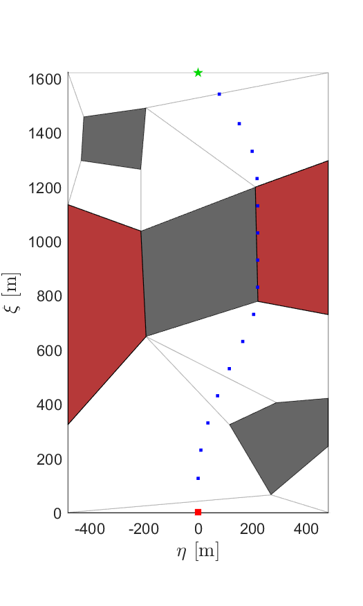
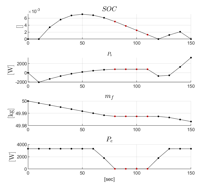
There is growing interest in using autonomous electric and hybrid-electric drones (UAS) in aviation. These drones could be used for tasks like delivering packages or for air taxis and ambulances in cities. However, there are major challenges to overcome, such as managing energy use and meeting environmental rules, like limits on aircraft noise. To solve these problems, autonomous planning algorithms need to take into account both how the vehicle moves and how much energy it uses.
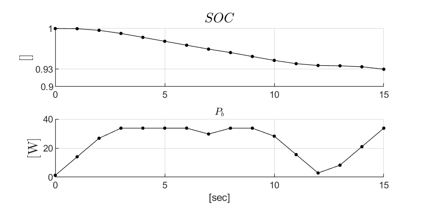
We consider two example scenarios in this work: 1) a hybrid-electric vehicle that must restrict engine usage when flying over regions with noise restrictions, and 2) an electric package delivery drone that must follow specific paths while also keeping its battery charged enough to complete its route. We solve these problems using an efficient optimization-based motion planner that we developed during prior work. Computational results for scenarios 1 and 2 are given in Figs. 1 and 2, respectively. In Fig. 1, the planner chooses a path that allows the vehicle to charge its battery before entering a noise-restricted area. In Fig. 2, the planner selects a route that avoids running out of battery, even though it means flying closer to one of the obstacles than desired. These results show the utility of accounting for the coupling between energy and motion dynamics during motion planning.
Research by Joshua Robbins, Ph.D. Student:
Motion planning is a key task in making vehicles, like self-driving cars, work autonomously. It acts as a middle step between the big-picture decisions about where the vehicle should go and the control systems that make the vehicle actually follow the path. The algorithms involved in motion planning use local information about the environment, which can be complicated, to create a safe path that avoids obstacles. These algorithms also need to make sure the vehicle moves smoothly and comfortably, while reducing risks or dealing with uncertainty. Since motion planning happens in real-time, the algorithms need to be fast and efficient to work properly.
We have developed an optimization algorithm for solving motion planning problems that takes advantage of a special way to represent the obstacle-free space, called a hybrid zonotope. Fig. 1 shows simulated trajectories using our optimization algorithm. Fig. 2 shows the solution times for the trajectories from Fig. 1. In Fig. 2, HZ denotes the hybrid zonotope constraint representation, while H-rep denotes halfspace representation, which is a more conventional approach. Gurobi is a state-of-the-art commercial solver. Solution times are reduced across the board using our solver with a hybrid zonotope constraint representation, often by one or more orders of magnitude. This demonstrates the utility of our approach for solving complex motion planning problems in real-time.
Research by Seho Park, Ph.D. Student:
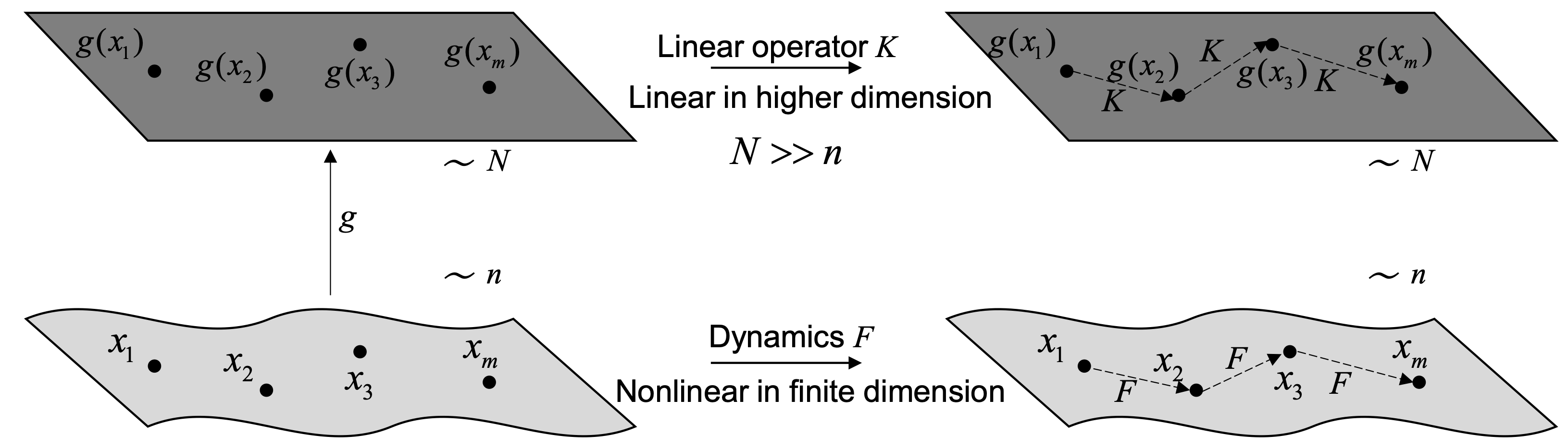
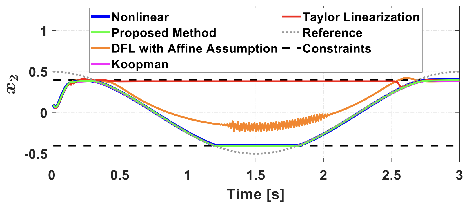
Optimal control problems for nonlinear dynamic systems result in nonconvex formulations, which entail large computational complexity. To reduce computational complexity for real-time implementation, linearization techniques are often applied to produce a linear system that approximates the nonlinear dynamics, with a first-order Taylor series expansion as the most common approach. However, Taylor series linearization typically has large error when the states are far from a fixed linearization point. On the other hand, lifting linearization methods provide a global linearization that can approximate nonlinear dynamics more accurately by using augmented states to capture nonlinear terms, as shown in Fig. 1.
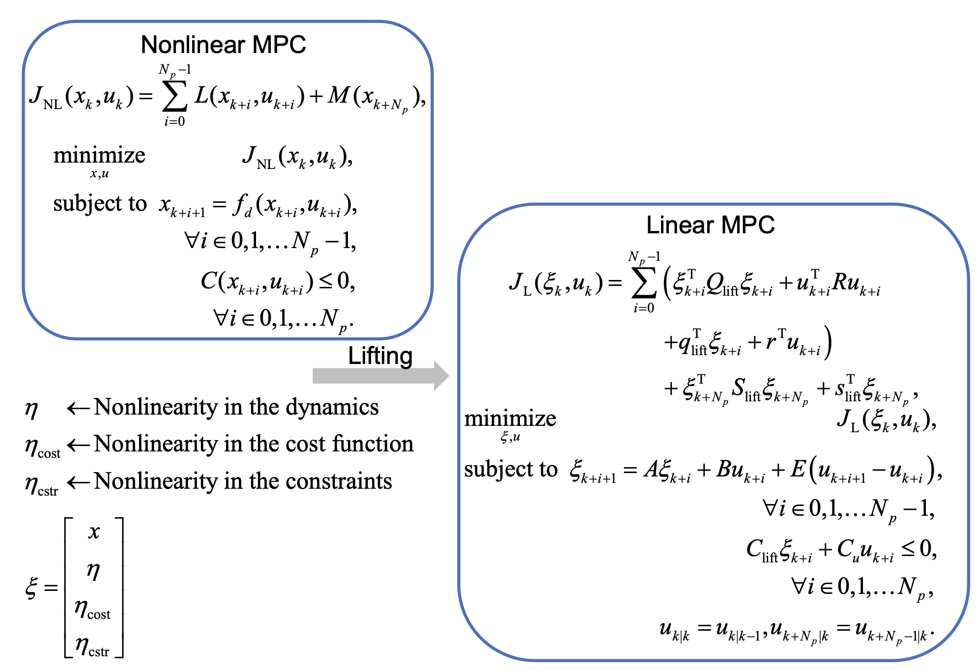
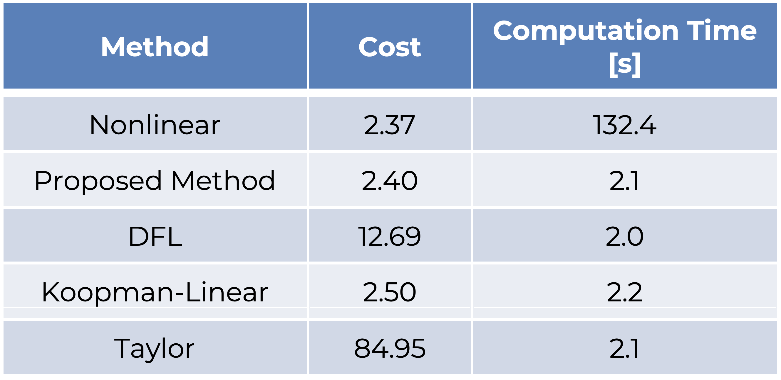
Given nonlinear dynamics, the proposed method approximates these as linear dynamics with an augmented state and noncausal term. Although the approximated dynamics are noncausal, the formulation is linear and can be used for prediction in linear model predictive control (MPC) with additional constraints as shown in Fig. 2. Figure 3 and Table 1 show numerical simulation results of nonlinear MPC and linear MPC with several linearization methods. The proposed method performs similar to nonlinear MPC at a fraction of the computation time.
Research by Jacob Siefert, Ph.D. Student:
Reachable and invariant sets are used to evaluate system performance and ensure constraint satisfaction in safety-critical applications while accounting for the effects of input, disturbance, and parameter uncertainties. For discrete-time systems, reachable sets are calculated by recursion over successor sets. For nonlinear systems, the complexity and nonconvexity of successor sets limit the scalability of existing approaches.
To improve scalability of calculating successor sets for nonlinear systems, this approach builds on our previous method for hybrid systems that leveraged hybrid zonotopes and a novel construct called a state-update set. Hybrid zonotopes can represent nonconvex, potentially disjoint sets efficiently by representing the union of an exponential number of convex sets using only a linear number of variables. Hybrid zonotopes are closed and have efficient identities for fundamental set operations including linear transformations, generalized intersections and Minkowski summations. A state-update set encodes all possible state transitions of a dynamic system. Using the state-update set, our work has developed a successor set identity using set operations that are efficient for hybrid zonotopes. The successor set identity and a visual representation of the identity is shown in Fig. 1. An extension to nonlinear systems is achieved by using an over-approximation of the nonlinear state-update set represented using a hybrid zonotope. In doing so, over-approximations of reachable sets are generated with linear memory complexity growth and computational complexity that scales linearly with the number of states.
To generate an over-approximation of the nonlinear state-update set, theoretical techniques to approximate nonlinear functions using Special Ordered-Set (SOS) approximations and bounds on SOS approximation error are leveraged. Our approach then efficiently converts SOS approximations into a hybrid zonotope. Fig. 2 shows a sinusoid (green), an SOS-approximation (red), and an over-approximation of the sinusoid (blue) represented as a hybrid zonotope.
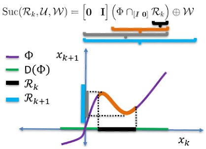
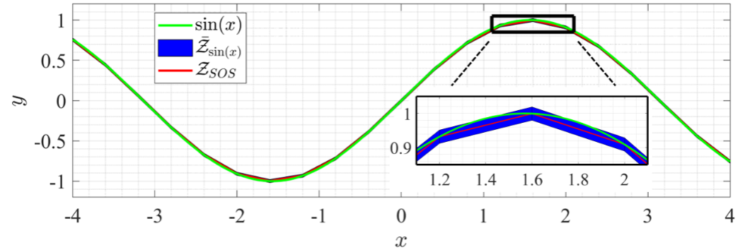
Fig. 3 shows reachable sets generated for pendulum-like dynamics in closed loop with a saturated feedback controller. Exact trajectories from randomly sampled initial conditions (green) are also plotted. As the reachable set is never significantly removed from sampled trajectories, it is shown that the over-approximation captures the nonlinear dynamics well, without excessive conservatism.
Research by Jacob Siefert, Ph.D. Student:
Reachable and invariant sets are used to evaluate system performance and ensure constraint satisfaction in safety-critical applications while accounting for the effects of input, disturbance, and parameter uncertainties. For discrete-time systems, reachable sets are calculated by recursion of precursor and successor sets.
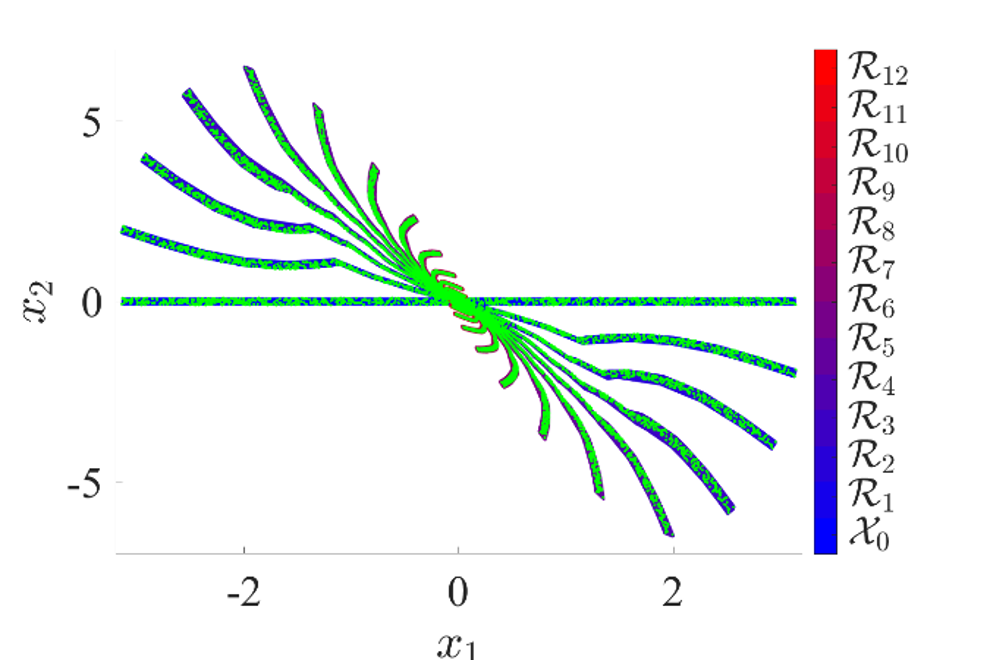
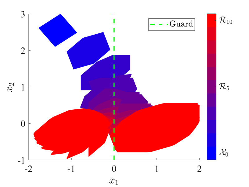
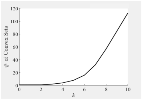
Problem: For hybrid systems with continuous and discrete dynamics, the complexity and non-convexity of precursor and successor sets limit the scalability of existing approaches. This is demonstrated using a numerical example for a piecewise affine system with only two regions separated by a so-called guard. Using convex approaches at each time step, reachable sets are partitioned along the guard and the appropriate affine dynamics are applied to each region. The guard and reachable sets are plotted in Fig. 1 starting from the set Xo. The number of convex sets for each time step is plotted in Fig. 2. The process of partitioning set results in more than 100 convex sets in only 10 time steps. In general, this process may result in the number of convex growing exponentially with time, significantly limiting the number of time steps over which analysis can be performed.
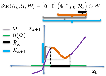
Method: To improve scalability of calculating successor and precursor sets, our approach combines a novel set representation called the hybrid zonotope with a novel construct called a state-update set. Hybrid zonotopes can represent nonconvex, potentially disjoint sets efficiently by representing the union of an exponential number of convex sets using only a linear number of variables. Hybrid zonotopes are closed and have efficient identities for fundamental set operations including linear transformations, generalized intersections and Minkowski summations. A state-update set encodes all possible state transitions of a dynamic system. Using the state-update set, our work has developed successor and precursor sets identities using set operations that are efficient for hybrid zonotopes. The successor set identity and a visual representation of the identity are shown in Fig. 3.
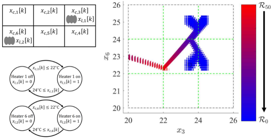
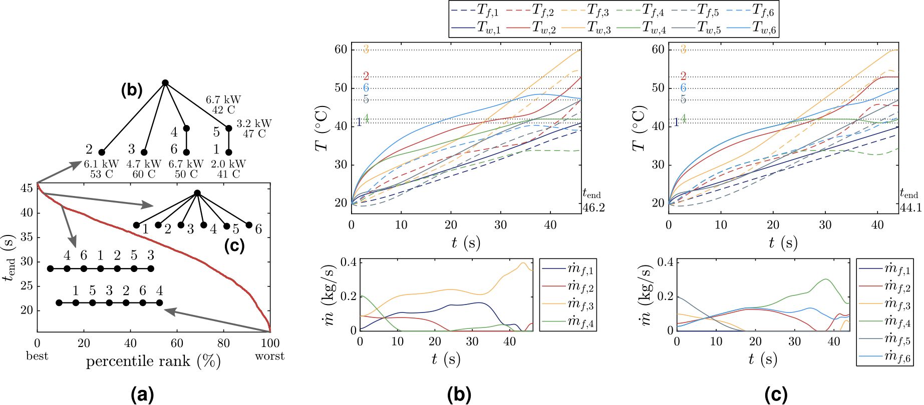
Results: Numerical results demonstrated the improved scalability of the approach over the state-of-the-art, reducing the memory complexity growth from exponential to linear. One numerical result compared the proposed approach and the state-of the-art for a room heating example with six rooms and two heaters. The room layout, heater on/off logic, and 50 backwards reachable sets from R50 are shown in Fig. 4. The proposed approach took 0.34 seconds to calculate while the state-of-the-art took over 202 seconds, resulting in the proposed approach being nearly 600 times faster. The proposed approach also resulted in a memory complexity 1/60th that of the state-of-the-art.
Research by Andrew Iezzi, Recent M.S. Graduate
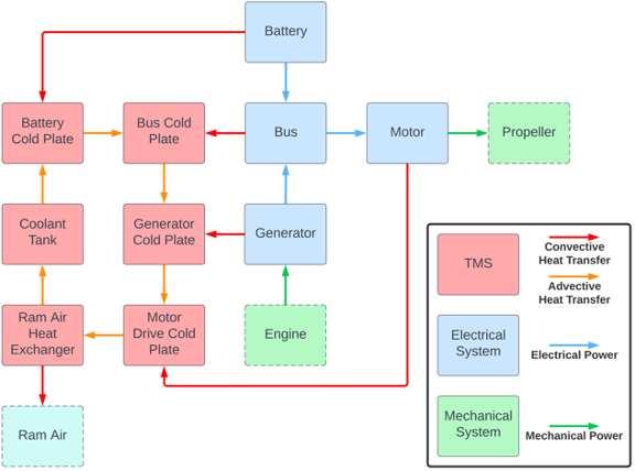
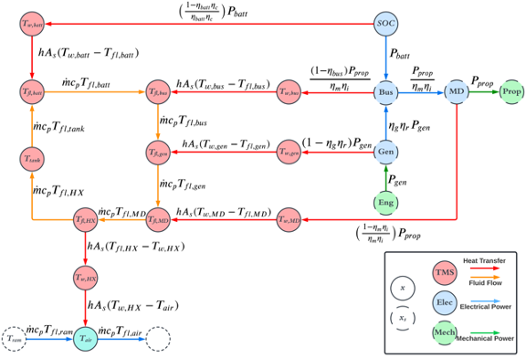
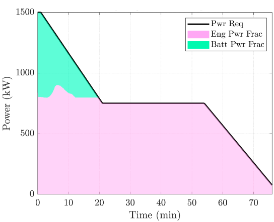
This research proposes a multi-disciplinary optimization framework for the design of aircraft electro-thermal energy systems. In this framework, components are modeled using a method called graph-based modeling, which uses the principle of energy conservation to model the transient states of a system with a set of compact and structured matrix equations. This representation allows multiple energy domains (electrical, thermal, mechanical, etc.) to be coupled and simulated together within a common modeling framework. This modeling approach is employed within an optimal control formulation to optimize both system-level design parameters and open-loop control trajectories. Case studies for a series hybrid-electric aircraft architecture demonstrate how key parameters of the electrical system, such as battery capacity, can be designed together with the associated thermal management systems for a representative transient flight.
Research by Seho Park, Ph.D. Student:
Most of the energy consumed by a hybrid electric vehicle (HEV) comes from fuel. The battery is used to improve efficiency of both propulsion and auxiliary loads like air-conditioning. The lifespan of the battery has a major impact on the cradle-to-grave sustainability and cost of the vehicle. Fig. 1 shows how one type of battery degradation, called SEI growth rate, varies as a function of current, state-of-charge (SOC), and temperature. However, most strategies for power management of HEVs focus on maximizing fuel economy without explicitly considering the impacts of control decisions on battery health. Therefore, this research develops a framework for integrated power and thermal management of HEVs that explicitly manages tradeoffs between fuel economy and battery degradation.
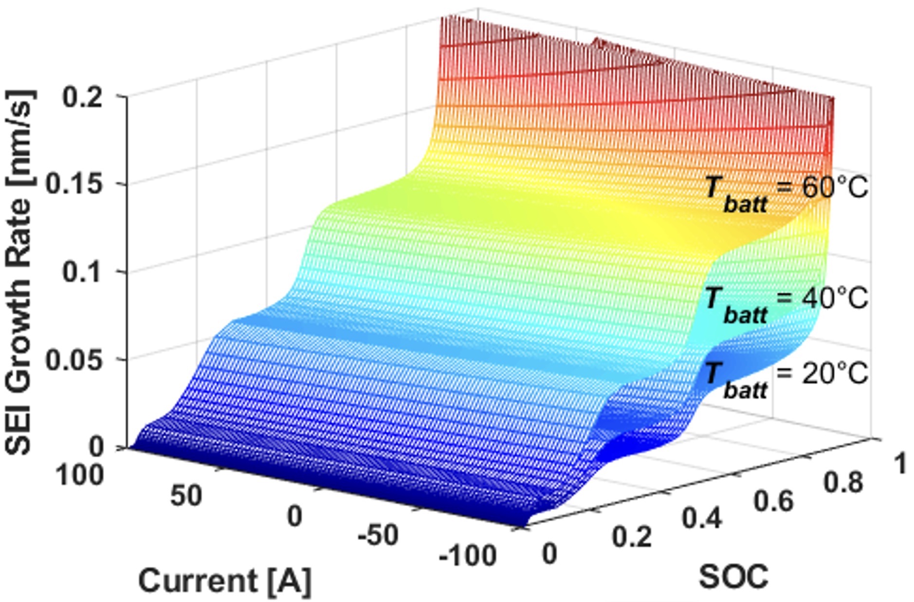
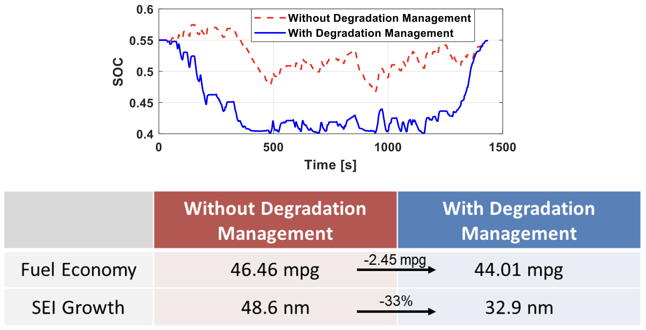
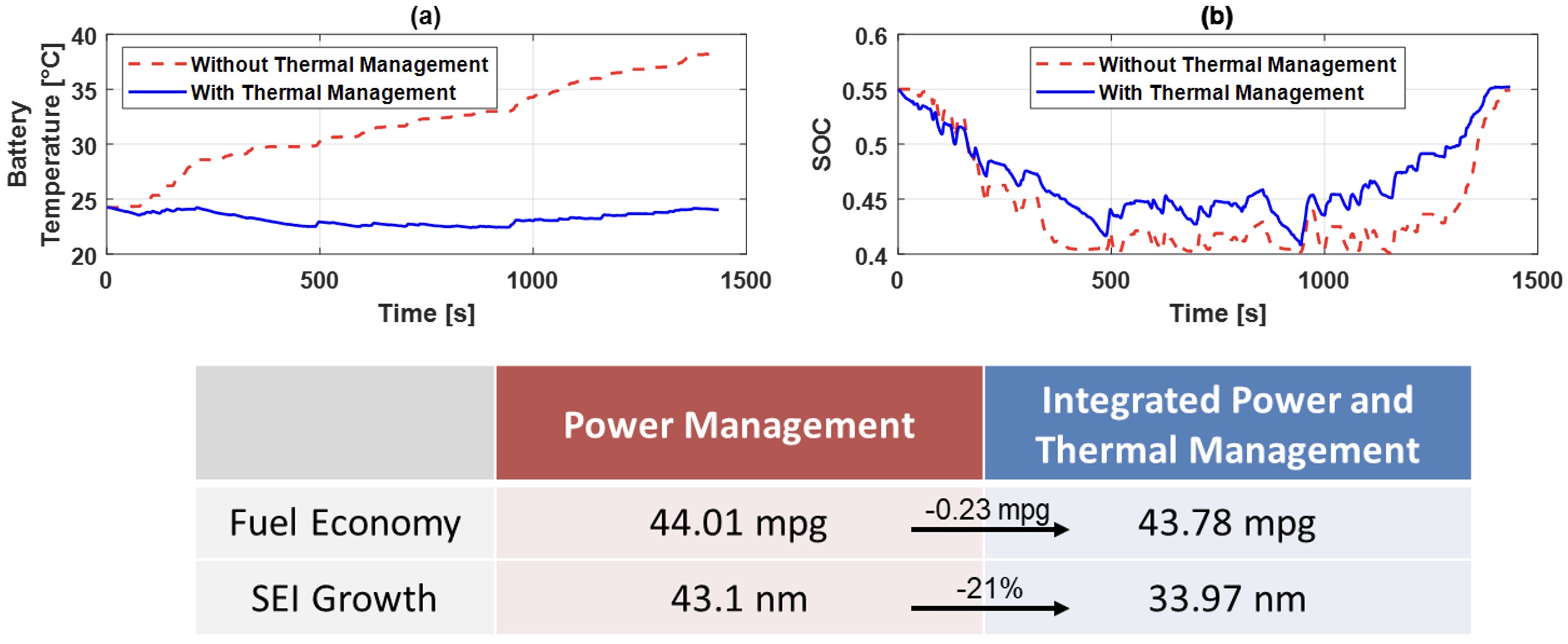
Fig. 2 compares controllers with and without degradation management over a simulated drive cycle. The former allows explicit tradeoffs between battery degradation and fuel economy to be made in maximizing the overall sustainability of the vehicle. Fig. 3 shows that also considering battery thermal management in the controller allows the battery degradation to be decreased by 21% at the cost of 0.23 mpg fuel consumption. Thus, integrating thermal management into the controller can greatly improve battery lifespan with a small impact on fuel economy.
consideration of battery degradation
(both cases consider battery degradation)
Research by Jacob Siefert, Ph.D. Student:
Set-based reachability analysis calculates all trajectories of a dynamic system subject to uncertainties in its initial condition, inputs, disturbances, and/or model. This analysis can be used to guarantee performance and constraint satisfaction of safety-critical systems, often by showing that reachable sets do not intersect unsafe regions. Exact reachable sets grow in complexity with time, becoming more computationally demanding to compute and requiring more memory to store. Established techniques (e.g., Interval Hull (IH-method) and Cascade Reduction (CR)) reduce exact reachable sets to lower-order approximations but are limited to discrete-time linear time-invariant (LTI) dynamics (for IH-method) or only guarantee that approximation error is bounded by an unknown exponential function (for CR). This research has developed a generalized over-approximation algorithm for computing reachable sets of discrete-time linear time-varying (LTV) dynamics, named DRAWBES, that leverages set representation to guarantee explicit error bounds. Furthermore, a periodic implementation of DRAWBES, DR-PPB, demonstrates that DRAWBES reduces over-approximation error AND computation time as compared to existing methods, while also providing explicit error bounds.
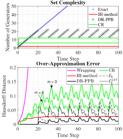
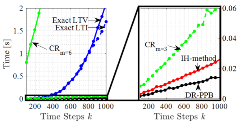
Fig. 1 compares set complexity and over-approximation error for exact and over-approximation methods, while Fig. 2 compares computation times. Exact reachable set complexity grows unbounded, while approximation methods exhibit bounded complexity. A key contribution is that DRAWBES produces explicit error sets, ε_k and ε_k^LTI, that bound the over-approximation error. The distinction between these two error sets is that ε_k^LTI can be pre-computed prior to reachability analysis but is limited to LTI dynamics, whereas ε_k must be computed online but is valid for LTV dynamics. As shown on the lower subplot of Fig. 1, these error sets provide upper bounds on the over-approximation error of DR-PPB, which itself has the least error of any method. As shown in Fig. 2, computation times for exact method grow super-linearly with the number of time steps taken, while approximation methods grow linearly. DR-PPB has tuning parameters that can be adjusted to balance over-approximation error, set complexity, and computation time. For the choice of tuning parameters in this case study, DR-PPB has higher set complexity than the existing methods but avoids performing over-approximations at every time step, resulting in the lowest computation time.
Previous Projects (conducted at the University of Illinois)
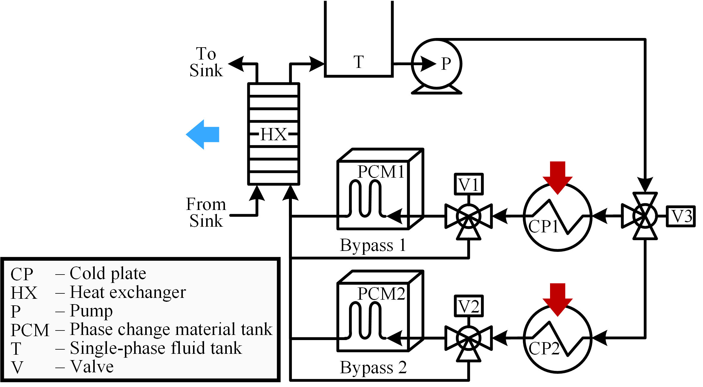
A rapid increase in the electrical power on board vehicles has presented significant challenges to their thermal management. One proposed solution for large vehicles is the inclusion of thermal energy storage (TES) modules containing phase change material (PCM) to quickly absorb large thermal loads, buffering fast thermal transients to reduce peak cooling requirements. However, the inherent nonlinearity and multi-timescale nature of systems with phase change energy storage must be addressed in control design. This research proposes a hierarchical hybrid model predictive control (MPC) framework to meet this need. A hierarchical control framework coordinates between the relatively slow phase change dynamics of the PCM and the relatively fast dynamics excited by pulsed loading. Switched linear models are used to approximate nonlinear dynamics across a wide range of operating conditions, resulting in hybrid MPC formulations that balance between accuracy of model representation and computational burden. The proposed approach is demonstrated in simulation on a candidate thermal management system with multiple TES modules, as shown in Fig. 1.
Many energy systems require control frameworks that can manage dynamics spanning multiple timescales and can make decisions for both continuous and discrete inputs. This research meets this need for a class of switched power flow systems modeled using graphs. Conditions are provided under which each mode of these models belongs to the class of cooperative systems. These conditions relate to physical phenomena such as satisfaction of conservation equations, and therefore are inherently met by many of the energy systems found in buildings and vehicles, for example those used for thermal management
The overall objective of the control design is to track a reference trajectory for the rate of energy transfer to a system, subject to bounded uncertainty in the exogenous disturbances associated with its ability to dissipate energy to sinks. The hierarchical framework manages slow system dynamics over a long time horizon in the upper level while simultaneously leveraging fast dynamics in the lower level to improve performance and reject disturbances. By leveraging properties of cooperative systems, the controller has been proven to guarantee satisfaction of state constraints while also ensuring that a minimum bound on the rate of energy transfer to the system can always be achieved.
The applicability of this approach has been demonstrated in both simulation and experimental application using a fluid-thermal system with dynamic behavior representative of vehicle thermal management systems. Fig. 2 shows several key signals from the simulation. The top subplot Fig. 2 shows the ability of the controller to adhere to temperature constraints, despite significant disturbance and preview uncertainty. In the bottom subplot, it can be seen that the controller always allows at least a minimum "flight critical" heat load to be absorbed by the thermal management system. Beyond achieving at least the flight critical loads, the controller is designed to maximize achievement of additional "sheddable" loads, but has the authority to reduce (i.e., shed) the sheddable loads as necessary to avoid temperature constraint violations.
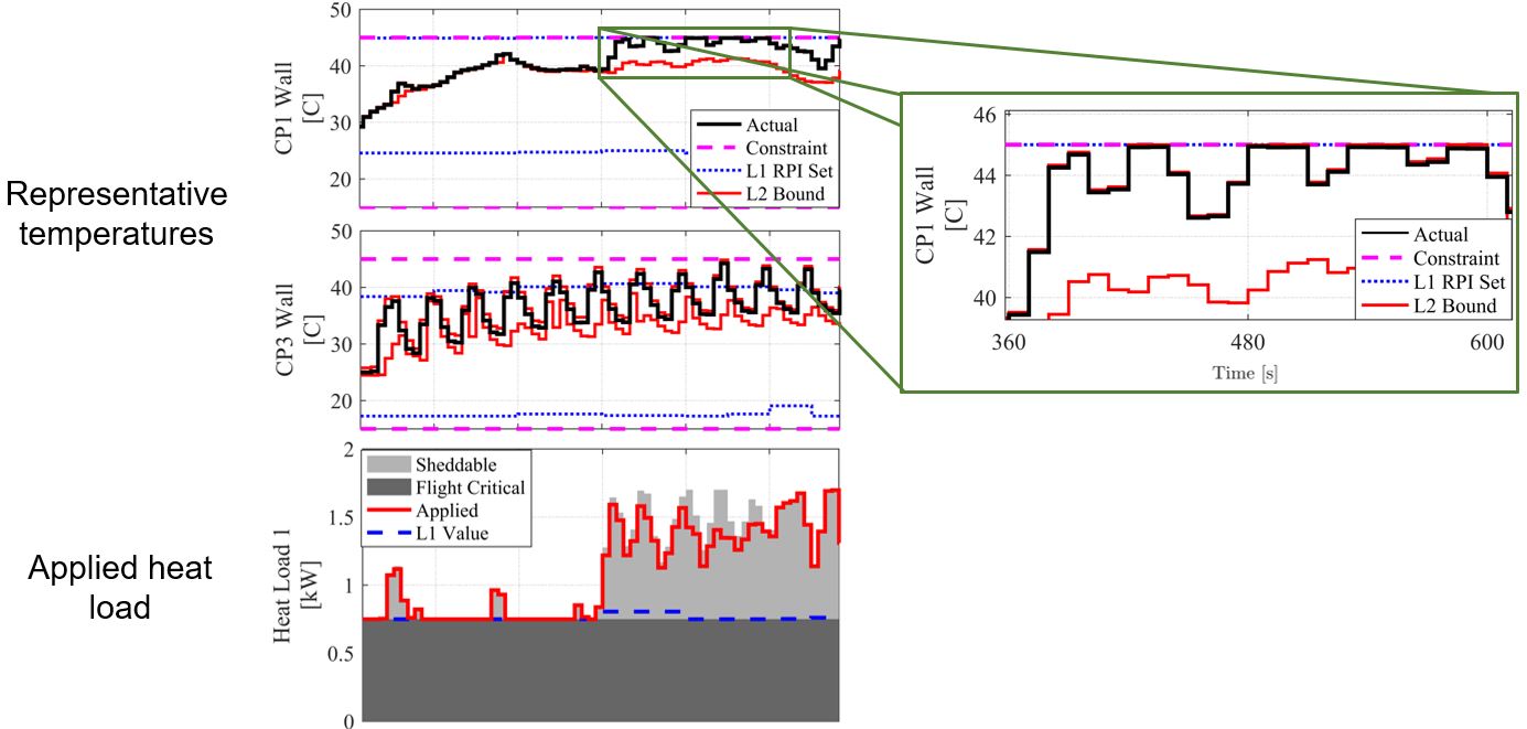
Fig. 3 shows a testbed used to experimentally validate the hierarchical control framework, and Fig. 4 shows an infrared video taken during a closed-loop experiment, exemplifying how temperatures throughout the system change dramatically as heat loads are applied to cold plates and actuators are switched to connect and disconnect thermal elements. Using this testbed, the high level of performance achieved by the hierarchical control framework in simulations has been shown to translate closely to experimental application.

Hierarchical control represents an enabling technology for the electro-thermal coordination of vehicle energy systems by employing a network of communicating controllers to coordinate behavior across multiple timescales, systems, and physical domains. As shown in the example aicraft hierarchical control framework of Fig. 2, controllers in the upper control layers coordinate high-level behavior at a relatively slow update rate and communicate references down the hierarchy to be tracked by faster-updating controllers responsible for managing specific subsystems and actuators. While only four control levels are shown in the example framework of Fig. 1, more levels can be added as necessary to match the timescales present in the system.
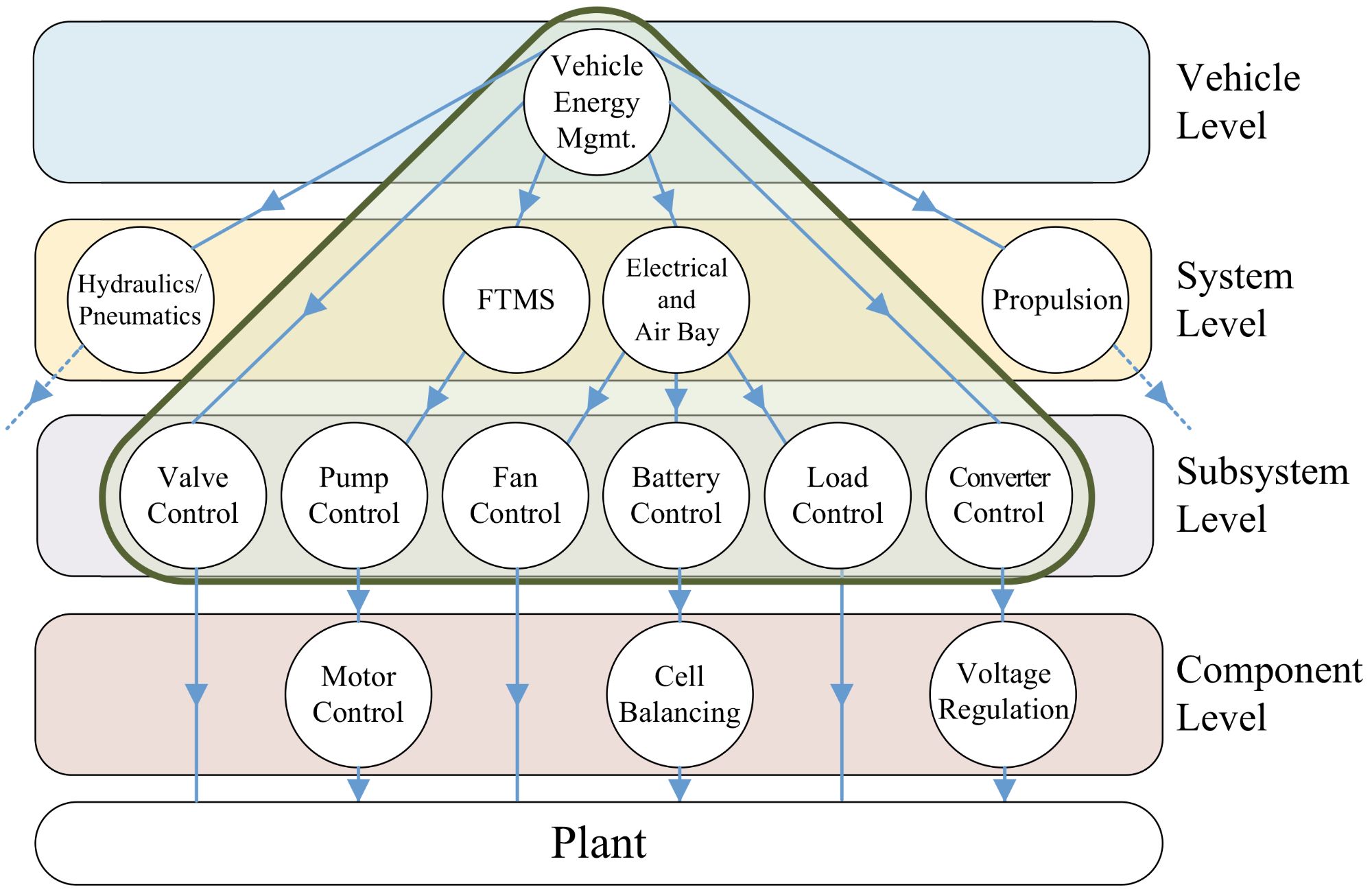
When advance knowledge of the vehicle task and/or anticipated environmental conditions is available, proactive action can be taken to optimize operation, for example by pre-cooling thermal storage elements in advance of large heat loads, or by strategically shedding or rescheduling the operation of non-critical electrical systems when thermal limits are predicted to be exceeded.
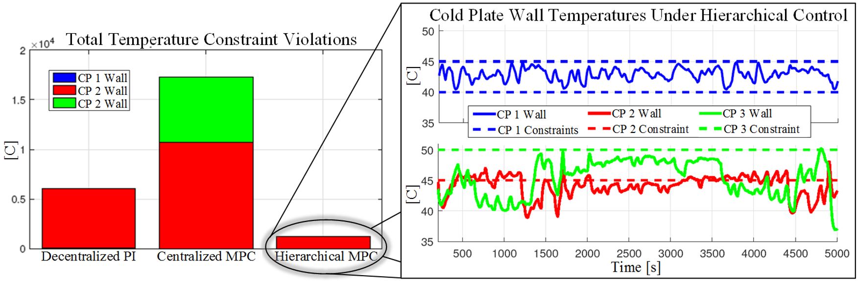
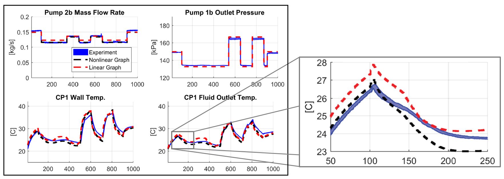
The left plot of Fig. 2 shows a comparison of graph-based hierarchical Model Predictive Control (MPC), centralized MPC, and decentralized proportional-integral (PI) control as applied to an experimental testbed representative of an aircraft fuel thermal management system (FTMS), subject to heat loads from electrical equipment. The hierarchical controller performs significantly better in maintaining desired bounds on cold plate (CP) temperatures due to its ability to coordinate both slow and fast dynamics, including compensating for unknown disturbances and model error.
Electro-thermal hierarchical control has also been demonstrated by hardware-in-the-loop implementation in which the plant consists of a real-time simulated air bay and electrical system coupled to a physical fluid-thermal testbed, as shown in Fig. 3.
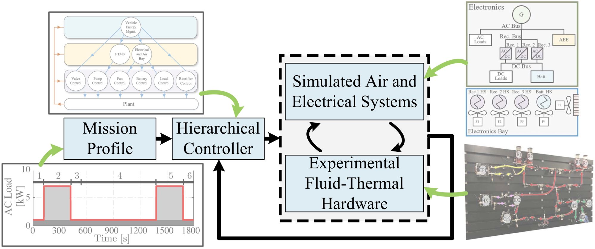
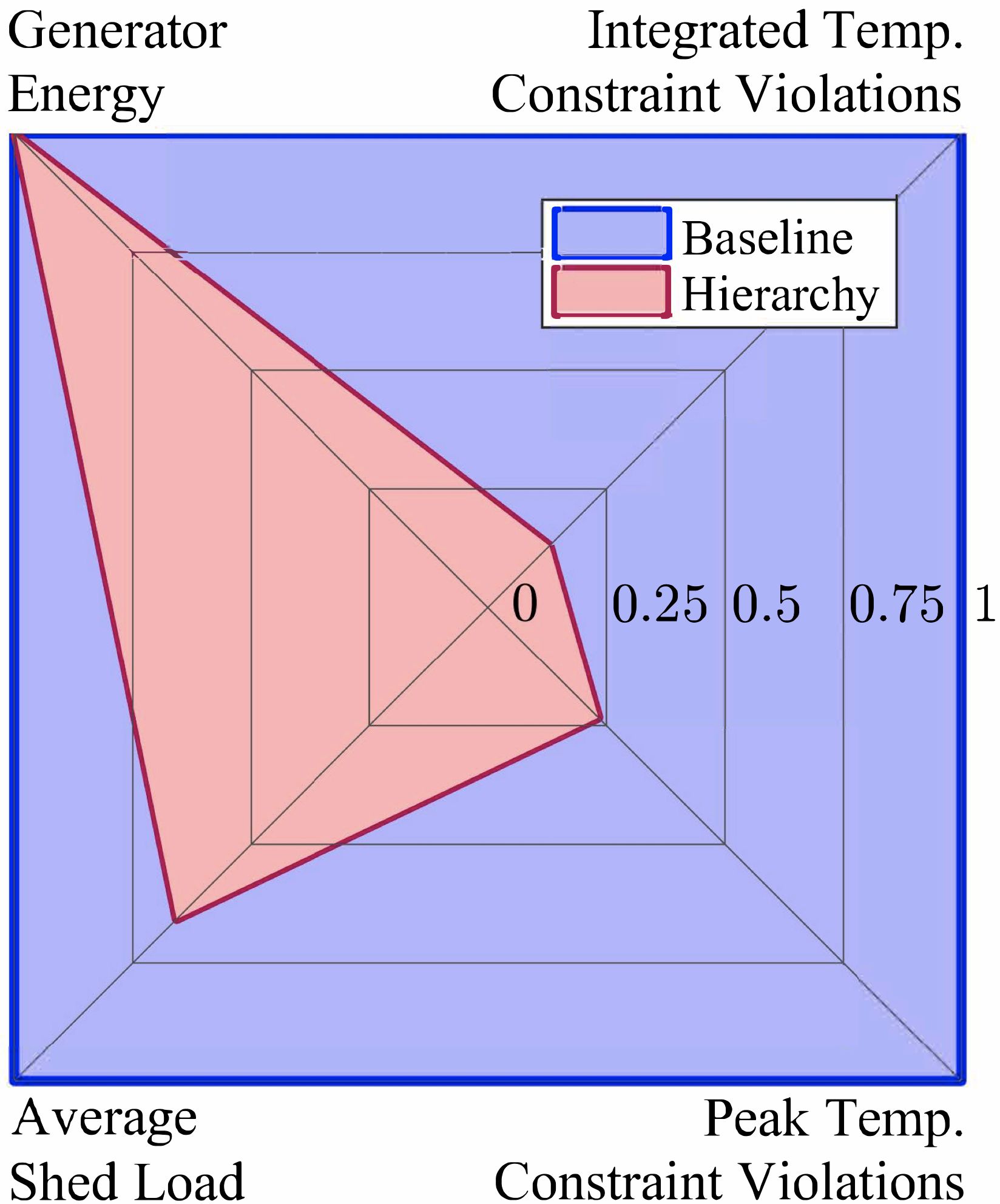
In this demonstration, hierarchical control has been shown to enable aircraft electrical systems to supply 1.5x more energy to on-board equipment as compared to a baseline control approach, while simultaneously consuming the same power from the generator and reducing temperature limit violations by 4-8x. This is depicted in Fig. 4, where the "shed load" refers to the extent by which electrical power must be decreased from a desired mission profile due to the system encountering thermal limitations or other operational constraints.
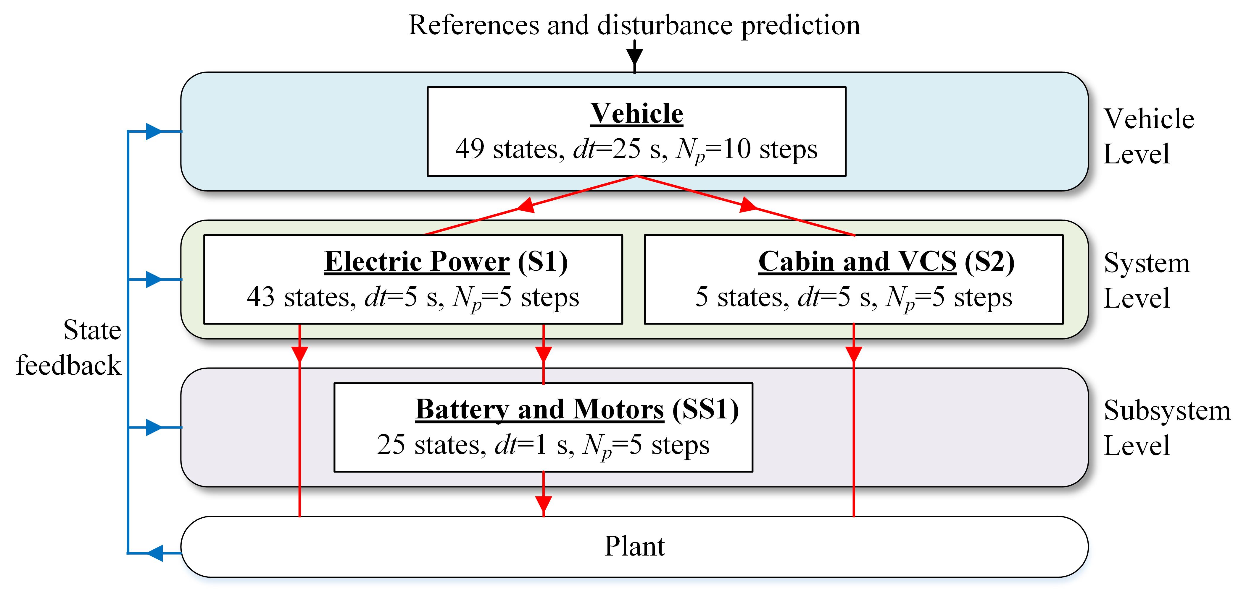
This research develop a hierarchical control framework to manage the electro-thermal dynamics of an automotive electric vehicle (EV) powertrain. As shown in Fig. 1, the upper levels of the hierarchical control framework provide long-term planning and coordination, while the lower levels leverage their faster update rate to compensate for model and disturbance error, improving the tracking performance and constraint satisfaction.
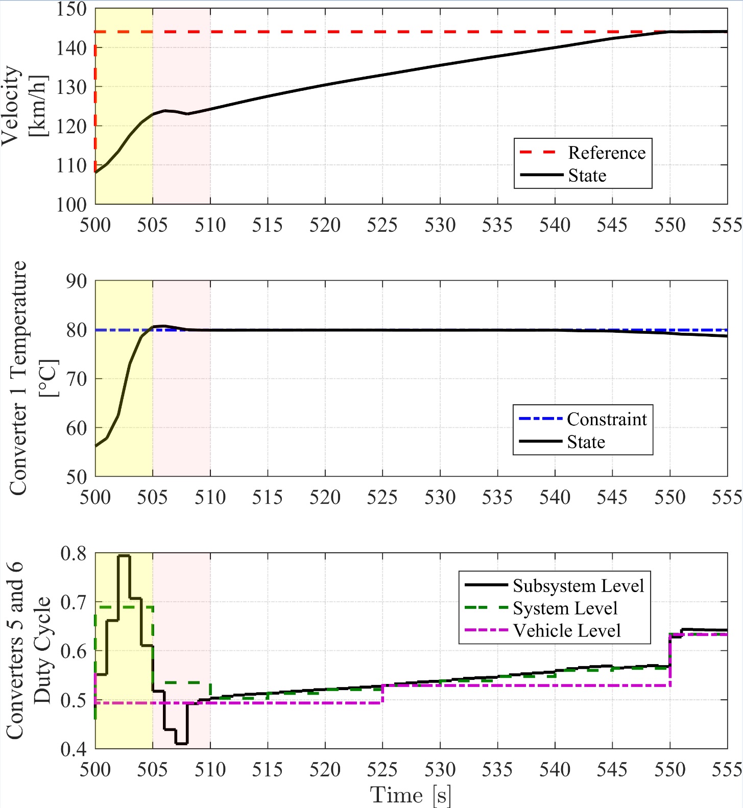
The performance of the hierarchical control framework is validated through a simulation-based case study in which the controller manages trade-offs among competing electrical and thermal goals, including between tracking objectives and thermal constraint enforcement. The results of the case study indicate that the energy management controller coordinates the powertrain components to achieve high tracking performance while avoiding significant violation of constraints. This is exemplified in FIg. 2, where the converter duty cycle is reduced in the subsystem level of the hierarchical framework from 505-510 seconds (bottom subplot) to reduce forward acceleration (top subplot) so that temperature constraints are not violated (middle subplot).
As new thermal management system applications and requirements emerge, engineers must learn how best to meet new needs, sometimes without the benefit of design heritage or the associated expert knowledge for particular systems. Thermal management system architecture design problems can have a vast design space that is cognitively difficult to navigate, motivating efficient systematic design methods with the flexibility to explore and assess new configurations. This research develops a design framework supporting comprehensive exploration of the class of single phase fluid-based cooling architectures shown in Fig. 1.
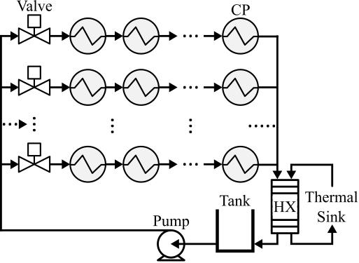
The candidate cooling system architectures are represented using labeled rooted tree graphs. Dynamic models are automatically generated from these trees using a graph-based thermal modeling framework. Optimal performance is determined by solving an appropriate fluid flow control problem, handling temperature constraints in the presence of exogenous heat loads to maximize thermal endurance. Case studies are performed in simulation, with components having variable sets of heat loads and temperature constraints. Results include optimization of thermal endurance for an enumerated set of 4,051 architectures, as shown in Fig. 2.
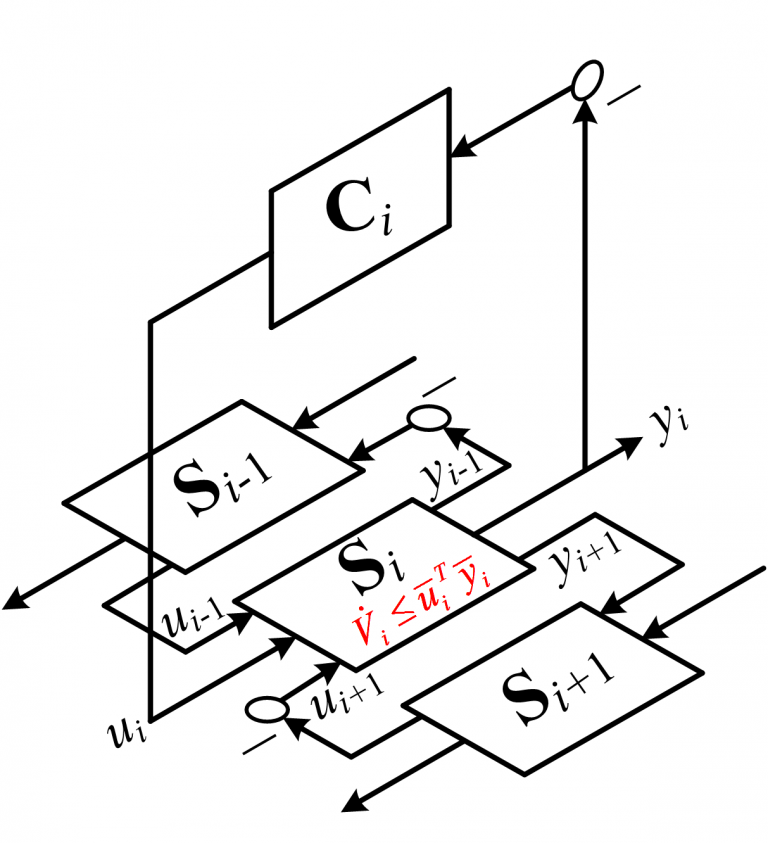
This research provides a framework for guaranteeing stability of energy systems controlled by decentralized or hierarchical MPC frameworks, including under the switching on and off of paths for energy transport within a system as actuators and components switch between modes of operation. This is achieved by analyzing the passivity of systems modeled as graphs, where a storage function can be applied to ensure that passivity is preserved under coupling between switched subsystems and in feedback connection with controllers, as shown in Fig. 1. The structure of the graph-based models allows a set of inputs and outputs to be determined that render each subsystem passive while admitting a nonlinear control-affine model representation that is applicable to a wide class of systems. MPC-based control formulations for each subsystem can then be augmented with decentralized passivity-based constraints to guarantee closed-loop stability under switching.
To facilitate model-based control, a dynamic graph-based modeling approach has been derived by applying the conservation of energy and mass to physical components and systems. Coupling between system elements is succinctly embedded in the structure of interconnections of a graph, allowing awareness of this coupling to be exploited for model-based control and leveraged in formal analysis of stability and robustness.
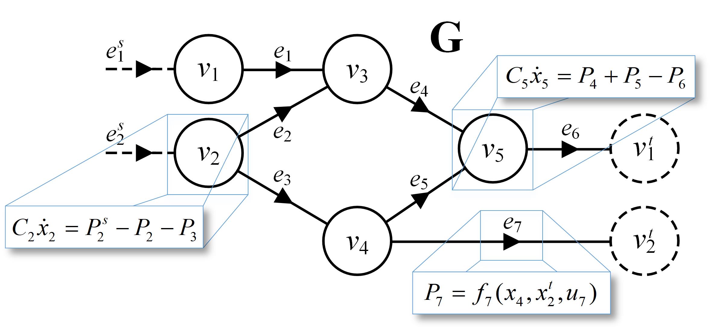
Fig. 1 shows a notional example of an oriented graph, which consists of an interconnection of vertices (circles) and edges (lines). When modeling a system as a graph, capacitive elements that store energy, or mass, are represented as vertices. Paths for the transport of energy, or mass, between storage elements are represented as edges. Conservation equations are then applied to develop dynamic models of the vertex states. Graph-based models of components can be derived individually and then assembled to form complete system models. This modularity facilitates representation of a wide range of vehicle energy system scales and configurations.
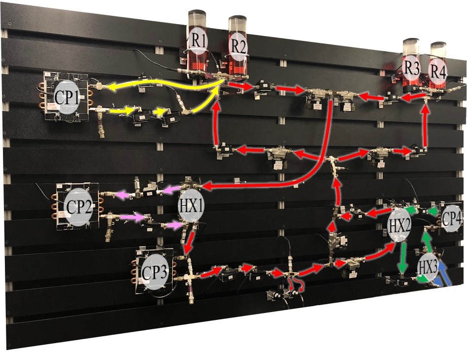
The graph-based modeling framework has been validated with experimental data collected from a testbed constructed by members of the Alleyne Research Group. This testbed, pictured in Fig. 2, has been designed as a “thermal fluid breadboard” to facilitate the rapid reconfiguration of components, allowing many different system architectures to be represented.
Comparisons of experimental data to both nonlinear and linearized graph-based models have demonstrated the ability of the proposed modeling framework to accurately describe both the hydrodynamic and thermodynamic behavior of thermal fluid systems. Several traces from such comparisons are shown in Fig. 3.
In collaboration with the Center for Integrated Thermal Management of Aerospace Vehicles (CITMAV), this research seeks to meet the challenges of managing thermal energy and enforcing operational constraints for high-performance aircraft. To achieve these goals, a Model Predictive Controller (MPC) is implemented that utilizes preview of upcoming loads and disturbances to prevent temperature constraint violations. Case studies on an experimental testbed demonstrate improved performance of these proactive control approaches as compared to traditional reactive control designs.
Fig. 1 shows the CITMAV experimental testbed, designed to be a simplified version of an aircraft fuel thermal management system (FTMS). Fig. 2 shows a schematic of the testbed. The system consists of two heat loads (high and low frequency) cooled by heat exchange with a chilled loop.

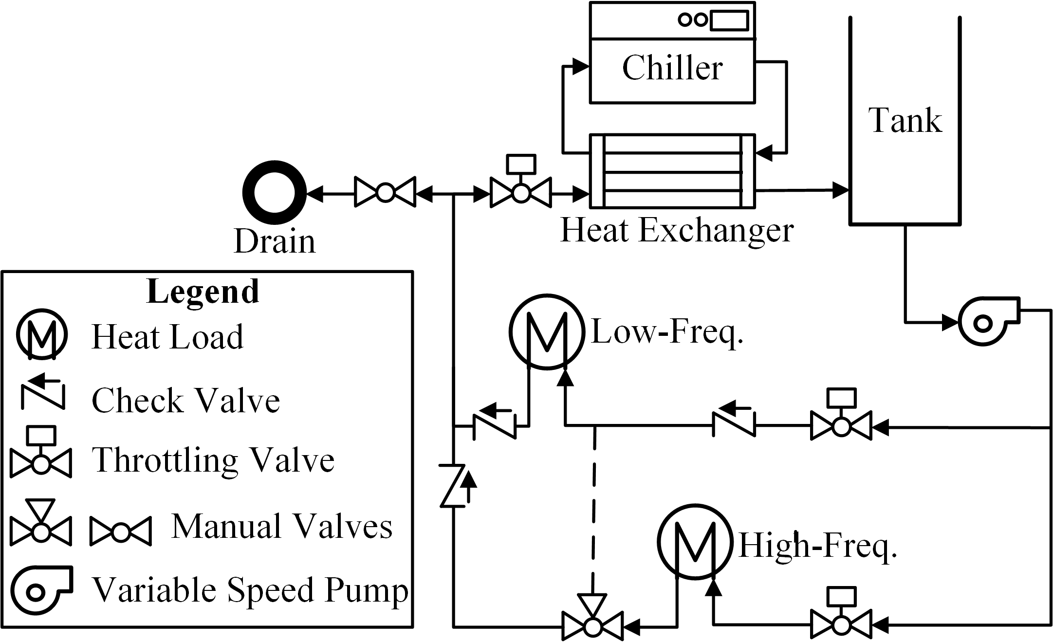
The system is modeled as an oriented graph, as shown in Fig. 3, where vertices of the graph represent dynamic temperature states of the system and edges of the graph represent power flow between the vertices, capturing heat transfer via fluid flow and energy exchange with heat loads and thermal sinks. This graph-based model is then used to design an MPC for thermal management.
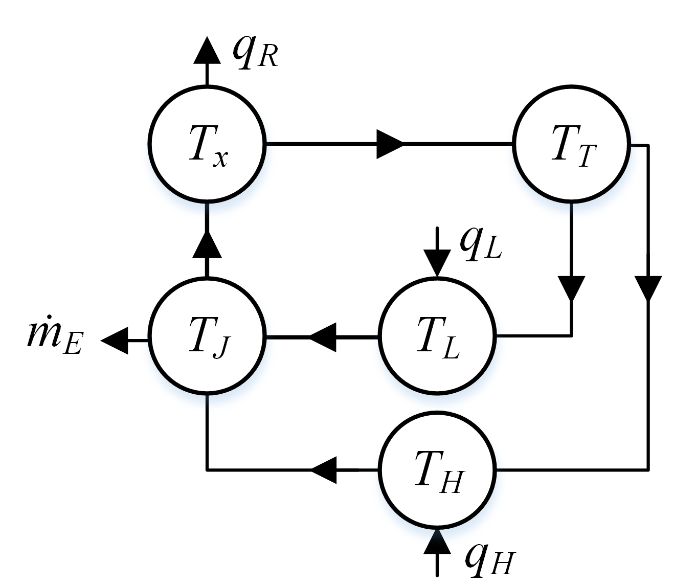
Fig. 4 compares the performance of the MPC (the “proactive” controller) against that of a PI controller (the “reactive” controller). In these results, the MPC receives a 30 second preview window of the upcoming low frequency heat load, representing an operational profile that may be known in advance as part of an aircraft’s mission. The proactive controller increases the mass flow rate 30 seconds prior to the onset of the first step in heat load. This is a result of the preview information received by the controller about the upcoming load, and has the effect of pre-cooling the low frequency heat load bay to prepare for the upcoming heat load, preventing a significant violation of the constraint later on. By contrast, the reactive approach does not increase the mass flow rate until after the temperature exceeds the reference, by which time it is too late to prevent significant overheating.

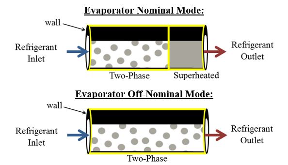
The dynamics of energy systems can very greatly with operating conditions. These systems can be captured in modeling by treating them as a collection of distinct operating modes, each with its own model formulation. Switching the model between these modes as a function of states and inputs allows the system to be described across a wide operational envelope. For example, the switched moving boundary modeling approach for multi-phase evaporators incorporates modes both with and without superheated flow at the refrigerant outlet as shown in Fig. 1.
Controllers for these systems can also benefit from a switched framework as shown in Fig. 2, allowing for the development of model-based control laws for each mode.
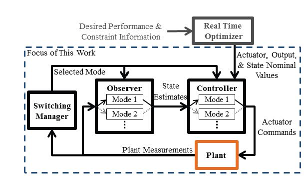
This research proposes a switched Linear Quadratic Gaussian (LQG) design to rapidly drive the system operation between modes and to perform regulation once the desired mode of operation has been achieved. Stability analysis of the closed-loop switched system is presented, and application of the control approach in both simulation and on an experimental VCS testbed demonstrate the success of the control design.
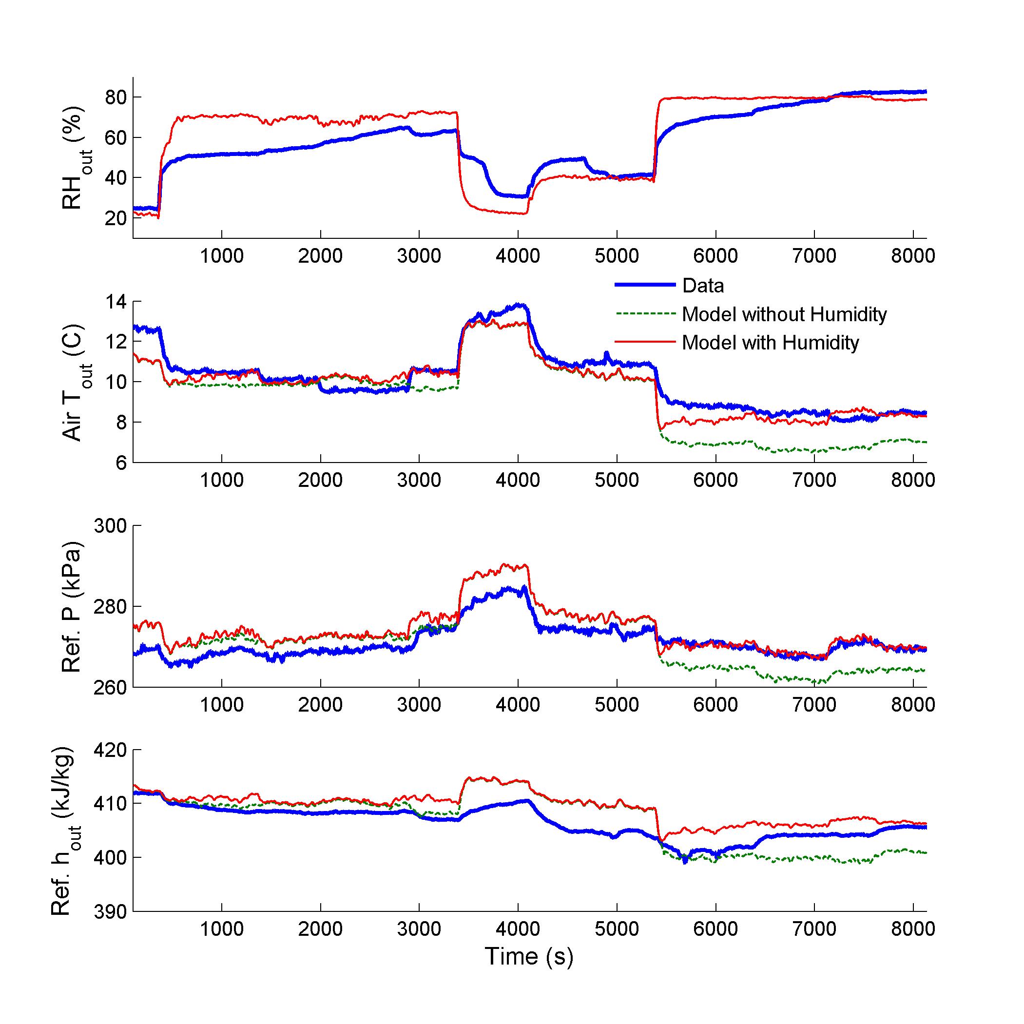
The effects of air humidity on the performance of refrigerant-to-air heat exchangers in vapor compression systems (VCSs) are non-negligible in modeling and control design for some applications. Such applications include both those in which the ambient humidity is expected to vary greatly over time and those in which control of the air outlet humidity is desired. In this research, a control-oriented heat exchanger model is developed that captures the effects of changing inlet humidity and predicts the outlet humidity and condensate mass flow rate. As shown in Fig. 1, experimental validation demonstrates that the inclusion of humidity modeling improves the accuracy of the heat exchanger model during periods of relatively rapid condensate formation (the last 2500 seconds of Fig. 1), allowing the model to capture the most salient dynamics while maintaining computational and analytical simplicity.
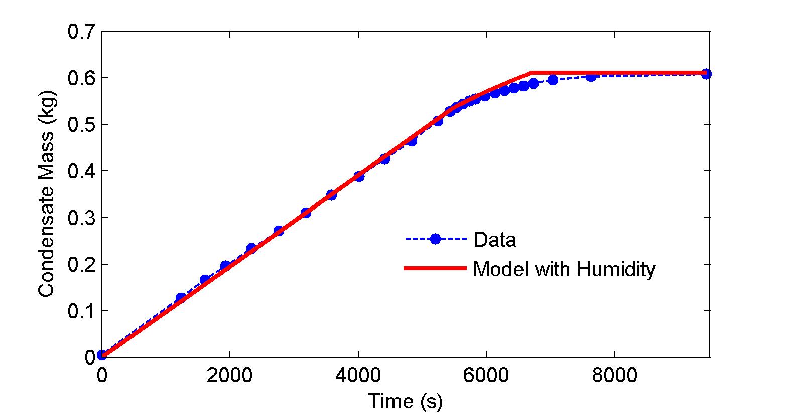
As shown in Fig. 2, which uses a different set of experimental data than in Fig. 1, the humidity models also accurately predict the mass of liquid condensate formed on the external surfaces of the heat exchanger.
Multi-phase heat exchangers for vapor compression systems (VCSs) are known as the most complex VCS components to model due to the highly nonlinear nature of the thermal dynamics that take place and the timescale separation between dynamics of different domains. This work compares the two most prevalent approaches used for first principles control-oriented modeling of heat exchangers, known as the finite volume (FV) and switched moving boundary (SMB) methods. The goal of this work is to provide insight to members of both academia and industry into the tradeoffs associated with the choice of approach for heat exchanger modeling.
The FV approach involves discretizing the heat exchanger spatially into an arbitrary number of equally sized CVs (control volumes), as shown in Fig. 1. In the SMB approach, the heat exchanger is divided into CVs corresponding to each refrigerant phase, as shown in Fig. 2. Unlike with the FV approach, the size of volumes can vary with time as phase flow lengths change.
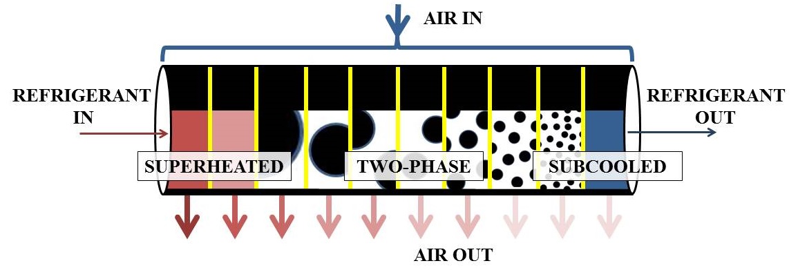
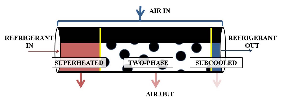
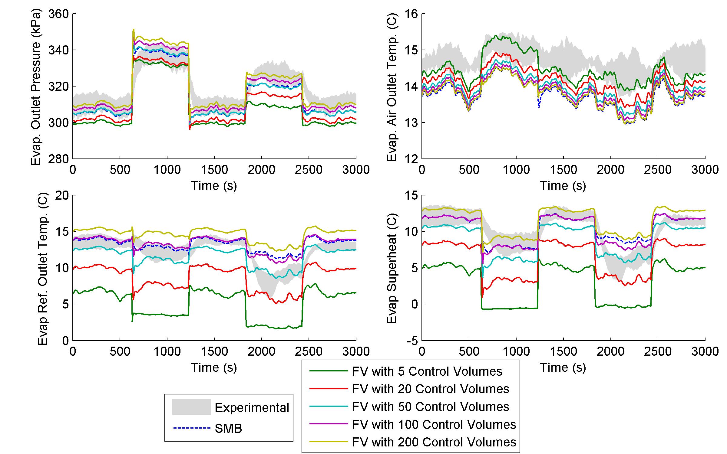
Fig. 3 shows simulation outputs for VCS models using both SMB and FV heat exchanger components. For the FV models, results from several different quantities of CVs are provided. These plots are superimposed over an envelope composed of the maximum and minimum values of experimental data from among five trials.
Fig. 4 shows the real time factor (RTF) of each model, defined as the length of time taken to run the simulation divided by the length of time that is simulated. As can be seen, the SMB model has a significantly smaller RTF, and therefore less computational complexity, than any of the FV models.
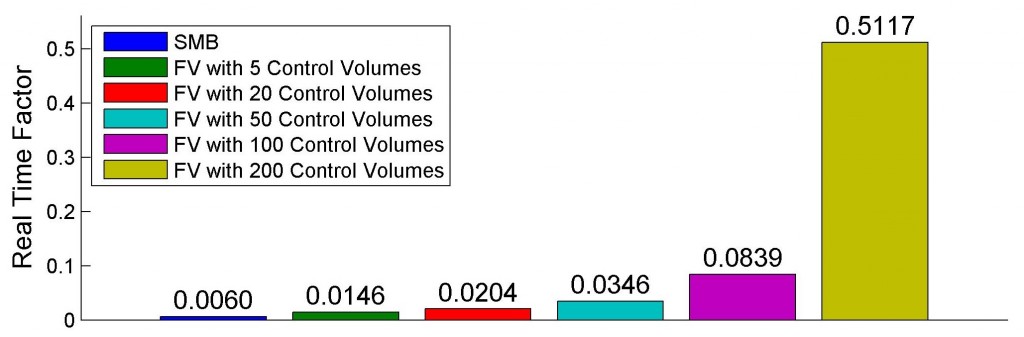
After close evaluation, a nuanced view of dynamic VCS simulation emerges from this work. If simulation speed is paramount, a SMB model can perform as accurately as a highly discretized FV model while executing significantly faster. Therefore, accuracy alone is not the sole forte of the highly discretized FV model. Instead, the intended use in target application and the need for flexibility of implementation may be the driving factors for selection of the FV model. This is because the added complexity of variable CV lengths in the SMB model render it more difficult to extend to various heat exchanger types and geometries than the FV model.